CD2D Equation – Explained – ParMooN
In This section , we are interested in solving the following Convection Diffusion reaction equation in a using ParMooN .
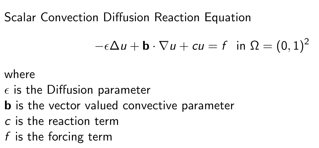
In the Following Square Domain as given below. with the following Parameters and Boundary Conditions
Epsilon = 1 ;; b(x) = 0 ;; b(y) = 0 ;; c = 0 ;; f = 0
Boundary Conditions:
Dirichlet on all sides
where y=1 u=1
u=0 elsewhere
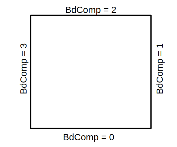
Note : We will be using ParMooN’s Internal Mesh generator for this purpose . The BDid’s will be defaultly generated in the order as shown above when ParMooN’s mesh generator is used.
STEP – 1 : EDIT THE USERCONFIG.CMAKE FILE
As mentioned in the previous section , we need to update 5 important paramters in the Userconfig.cmake section. Edit the file using by opening it with any text editor.
Dimension – 2D ; Equation – CD2D ; Parallelisation – SEQUENTIAL ;
Arhitecture – LINUX64 ; Ouput Folder : ../../ParMooN_Output/CD2D
Note : Change the output folder and the system architecture accordingly based on your system requirement.
Ignore the The MPI_IMPLEMENTATION part when the parallelisation type is selected as SEQUENTIAL , Since it will not be considered during compilation of cmake
# selection of dimension (2D 3D)
set(AParMooN_GEO "2D" CACHE STRING "Change AParMooN_GEO, to select the Dimensio of the problem")

# select this line accordingly to include your main program
set(AParMooN_MODEL "${PROJECT_SOURCE_DIR}/2DPrograms/CD2D_ParMooN.C" CACHE STRING "Enter to select the Main file of the model")

# selection of architect type (LINUX64 MAC64 INTEL64 TYRONE64 CRAY64)
set(AParMooN_ARCH "LINUX64" CACHE STRING "select the machine type")

#  selection of program type (SEQUENTIAL SMPI MPI OMPONLY HYBRID SCUDA)
set(AParMooN_PARALLEL_TYPE "SEQUENTIAL" CACHE STRING "select the parallel type")

#  selection of program type (MPICH OPENMPI INTELMPI CRAYMPI MACMPI)
set(AParMooN_MPI_IMPLEMENTATION "INTELMPI" CACHE STRING "select the MPI Implementation type")

# set the path to save the exe file ....................................................................................
set(AParMooN_OUTPUT_DIR_PATH "${CMAKE_SOURCE_DIR}/../ParMooN_Output/CD2D" CACHE STRING "select the model")
Once the Following changes are made , Save and close the Userconfig.cmake file
STEP -2 : BOUNDARY CONDITIONS – EXAMPLE FILE
In this we will include the boundary conditions specified for our model problem in the example file. As mentioned ( in the previous section ) the example file has to be included in the main executable file ( which is provided as “AParMooN_MODEL” in our Userconfig.cmake file. ).
In this case , we have provided the file “ParMooN/2D_Programs/CD2D_ParMooN.C ” as the main file . Open the file and check for the included example file in the Main file ( at the top of the code , after all the Library headers )
Things to Note :
1. Make sure that only one example file is included in the Main Program, others need to be commented out.
2,. The user can use any new/custom file as an example file and use that for compilation , given that it contains all the functions in the same structure ( as mentioned in this section )
3, If an “ifdef _TEST” block is present in the code, include the example file in the else block of that ifdef code only.
In our case, we could see the example being included as “sinelaplace.h”
#include "../Examples/CD_2D/SineLaplace.h" Open the Sinelaplace.h file, which is present in the above mentioned path to modify the BC for our problem.
Note : You can edit the existing file or create a copy of the existing file into another name and include that new example in the main file.
Here, I have made a copy of the Current example file into a new file called “TempDistribution.h” . I will be editing the boundary conditions for my problem in this file. SO I have replaced the previous sineLaplace.h file in the include section of the main program to ,
#include "../Examples/CD_2D/TempDistribution.h" Now open TempDistribution.h and edit the following functions to impose BC and Boundary Values
Boundary Condition :
Since we need to impose dirichlet on all boundary surfaces, we can code them as below in the boundCondition function
void BoundCondition(int BdComp, double t, BoundCond &cond)
{
    cond = DIRICHLET;
}
Note : Just in case , if we want to impose neumann boundary condition on side walls (BdId = 3 and 1 ) , then we can use the following code
void BoundCondition(int BdComp, double t, BoundCond &cond)
{
    if(BdComp == 1 || BdComp == 3 )
         cond = NEUMANN;
    else
         cond = DIRICHLET
}
Boundary Values :
Here we will Provide the prescribed boundary values for our problem in the boundValue function. In our case , we need to provide a dirichlet value of “1” on BdComp = 2 and “0” elsewhere
void BoundValue(int BdComp, double Param, double &value)
{
    if(BdComp == 2) value = 1;
    else value = 0;
}
Note : If the Boundary condition provided on the surface is Dirichlet , then the given value will be taken as Value of u. If the BC is provided as Neumann for a particular surface , then the given value given inside this function will be used inside the FE code as a Traction value ( grad(u) ) .
Bilinear Coefficients :
WE need to fill the bilinear Coefficients for this problem in the function BilinearCoeffs in the example file. For our model problem, we need to provide the following values inside the function.
Epsilon = 1 ;; b(x) = 0 ;; b(y) = 0 ;; c = 0 ;; f = 0
For CD2D, the format in which we need to fill the Values in the Coeff Array is ,
coeff[0] = Diffusion Parameter ( Epsilon )
coeff[1] = Convection Parameter ( b1 ) ( in x direction )
coeff[2] = Convection Parameter ( b2 ) ( in y direction )
coeff[3] = Reaction Parameter ( c )
coeff[4] = source term (f)
Based on this , we modify the function as below
void BilinearCoeffs(int n_points, double *x, double *y,
        double **parameters, double **coeffs)
{
  static double eps=1/TDatabase::ParamDB->PE_NR;
  int i;
  double *coeff;

  for(i=0;i<n_points;i++)
  {
    coeff = coeffs[i];
    //double *param = parameters[i];
    coeff[0] = eps;  // eps
    coeff[1] = 0;  // b1  ( X direction )
    coeff[2] = 0; // b2    ( Y direction )
    coeff[3] = 0; // c - reactoin

    coeff[4] = 0; // // force
  }
}
Note : in this case, the epsilon value is picked from the PE_NR value provided in the DAT file ( from TDatabase::ParamDB->PE_NR ) , We will enter that value in the next section inside the cd2d.dat (param) file.
Note : Being a Stationary problem , this problem does not have any Initial Contition . Further, we are not intrested in doing the error analysis , so we are ignoring filling the exact solution function also .
Refer Compilation workflow section for information on how to fill the exactValues function
STEP – 3 – BUILD AND COMPILE
Since we have edited our the required files, we can now BUILD our basic CD2D program using ParMooN
Navigate to the Root Directory of ParMooN ( Doing an “ls” from terminal in ParMooN root directory should reveal folders like 2DPrograms, 3DPrograms , src, FE ) , and create a new folder for BUILD purposes
mkdir BUILD
cd BUILD
Now run the cmake Process from the current BUILD directory
cmake ../The CMake should have executed Successfully . A Successfull exeuction of the CMAKE should produce these lines at the end of the output. Else check out the basic trouble shooting section or ParMooN forums for FAQ on troubleshooting
 -- Configuring done
 -- Generating done
 -- Build files have been written to: /home/thivin/PARMOON_CODES/ParMooN/BUILD
Now given that the cmake is run , you can run make using the command
make -j4Note : The -j parameter is used for compiling the programs using “n” number of processor threads. in this case -j4 means , I am compiling using 4 processor threads. Use a suitable number based on your system specifications.
The make file should be executed without any errors, A Successfull compilation will not show any “errors” at the end and it will end with the console similar to the one below.
[100%] Building CXX object CMakeFiles/parmoon_2D_SEQUENTIAL.exe.dir/2DPrograms/CD2D_ParMooN.C.o [100%] Linking CXX executable /home/thivin/PARMOON_CODES/ParMooN_Output/CD2D/parmoon_2D_SEQUENTIAL.exe [100%] Built target parmoon_2D_SEQUENTIAL.exeSTEP – 4 – SETTING UP FOR EXECUTION
Given that the executable is generated, it will be placed on the output directory ,specified in the Userconfig.cmake file.
In our case, it is going to be ” ../../ParMooN_Output/CD2D/” . So navigate to the directory and check whether the executable is present or not.
cd ../../ParMooN_Output/CD2Dexecuting “ls” from this directory should reveal the executable present in that folder . for 2D Sequential CD2D, the exe name will be parmoon_2D_SEQUENTIAL.exe
Now, we need to provide the param file which contains major information such as Mesh File, type of Mesh, Level of refinement of Mesh, Peclet Number, Direct Solver type , Discretisation type etc.
Copy a Sample Param file for cd2d ( cd2d.dat ) from the ParMooN code inside ReadIn folder.
Note : The readin folder contains a sample dat file for all of the modules (like TNSE3D, NSE2D ) inside it.
cp ../../ParMooN/ReadIn/cd2d.dat .Note : This copies the cd2d.dat file to our directory. Do not ignore the dot at the end of the command.
STEP 5 : MODIFYING PARAM FILES
Now, Open the param file with any file editor ( or vim for Command Line Interface ) and change the values accordinly for our simulation
MESH SELECTION :
For Mesh , in this case we are using ParMooN’s internal Mesh generator. we are using a square domain, so we are using a “UNITSQUARE.GEO” file and “UNITSQUARE.PRM” file. FOr internal mesh generation , we need to provide both .GEO file and .PRM file. Further, Since we are using internal mesh Generators, we need to set the MESH_TYPE as “0” and USE_PRM as “1”
BNDFILE:        ../../ParMooN/data/UnitSquare.PRM
----------------------------------------------------------------------
# MESH_TYPE = 0 (ParMooN geo mesh), 1 (Gmsh), 2(TetGen mesh)
----------------------------------------------------------------------
MESH_TYPE: 0
USE_PRM: 1
GEOFILE:        ../../ParMooN/data/UnitSquare.GEO
Note : 1.parMooN currently supports third party mesh formats such as “.mesh” file and “tetgen” file. If you want to use them, give the “.mesh” file in the GEO_FILE tag and choose the MESH_TYPE value accordingly
2, To use various geometries that are available within ParMoon Internal mesh gen , refer the “data” folder in ParMooN code folders.
MESH REFINEMENT :
This is for ParMooN Internal Mesh Generation only. Depending upon the levels provided here , the mesh will be uniformly refined in all directions. For our case, I am using the uniform refinement as “4”
----------------------------------------------------------------------
# number of uniform refinement steps at beginning
----------------------------------------------------------------------
UNIFORM_STEPS: 4
ORDER OF FINITE ELEMENT :
This allows us to set the order of finite element that we want to use. If we want to use Q1 we need to provide “1” and for Q2 “2” so on.
Note : For more Information regarding the elements available refer “Finite Elements : Theory and Alogorithm Sashikumaar Ganeshan , Lutz Tobiska – IIScPress and Cambridge University Press
----------------------------------------------------------------------
# order of ansatz space (=k)
#   i.e. P_k on triangles
#        Q_k on quadrangles
----------------------------------------------------------------------
ANSATZ_ORDER: 1
ERROR MEASUREMENT :
Set the MEASURE_ERRORS:value as “1” to perform the error analysis. For this the exact solution should be provided in the example file ( included in the main program )
MEASURE_ERRORS: 1FINITE ELEMENT DISCRETISATION TYPE :
Select which type of FE Discretisation that you have to use to solve the problem.
For Standard Galerkin, I have used the value 1 for our model problem
Note : For more Information regarding the Discretisations available refer “Finite Elements : Theory and Alogorithm Sashikumaar Ganeshan , Lutz Tobiska – IIScPress and Cambridge University Press”
-----------------------------------------------------------------
# GALERKIN  : 1
# LOCAL_PROJECTION  : 14
# SUPG/SDFEM : 2
# UPWIND : 3
# GLS : 6
# HEATLINE : 100
-----------------------------------------------------------------
DISCTYPE:  1
PECLET NUMBER :
To provide epsilon value, The epsilon value is provided in the DAT file as “1/eps” value.
-----------------------------------------------------------------
# Peclet number eps=1/PE_NR
-----------------------------------------------------------------
PE_NR:  1
SOLVER TYPE :
Select the type of solver that you need to use for solving the linear system of equations that arise from the FE discretisations.
We will use Direct Solver ( UMFPACK ) for our computations.
-----------------------------------------------------------------
#   Solver type Selection
# 0  AMG_SOLVE   Algebraic Multi Grid Solver
# 1  DIRECT      Direct Solver which makes use of UMFPACK and LAPACK Solvers to Solve the system
-----------------------------------------------------------------
SOLVER_TYPE:1
We have completed filling all the necessary parameters, now save the cd2d.dat file and close.
STEP – 6 : FINAL EXECUTION
Now that , we have set up the essential part for the execution we can run the executable to get the result.
./parmoon_2D_SEQUENTIAL.exe cd2d.datThe execution should not end in between due to any errors or it should not have any errors in the console.
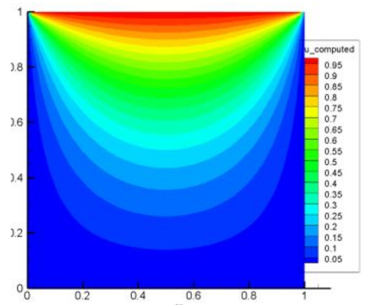
STEP – 7 : VISUALISATION
ONce the execution has been completed, the VTK file will be generated in the “VTK” folder within the current directory where we have executed the program.
To view the result, Open Paraview, then open the “unitCube.vtk” file generated in the VTK folder and click OK.. once loaded, click “APPLY ” on the properties window left pane to get the visualisation.
For the above given problem , the Visualisation should be similar to the figure shown below